DIN 934 Hex Nut Dimensions and Standard Specifications
The Ayask Steel Engineering Team writes for plant buyers, project engineers, and procurement teams sourcing custom steel components as per drawing. Our perspective comes from 40+ years of manufacturing rolling mill components, replacement parts, and fabricated-and-machined assemblies where fit, function, delivery, and documentation all matter.
- 40+ years of continuous manufacturing operations
- Experience with replacement parts, shutdown support, and project-based industrial manufacturing
- Built-to-print fabrication and machining for OEMs, EPCs, steel plants, and maintenance teams
DIN 934 is the legacy German standard for hexagon nuts with metric coarse and fine pitch threads. For manufacturing, inspection, and procurement teams, the practical value of the standard is simple: it defines the nut envelope dimensions, identifies the applicable product grade, and points to the related thread and technical-delivery standards needed to buy or manufacture compatible hardware correctly.
This article is based strictly on the supplied October 1987 DIN 934 source and the DIN 13 extract available in this repo. It is written as a technical guide for engineers and buyers who need the actual DIN 934 hex nut dimensions, not a generic overview.
The supplied DIN 934 document states that it should be used together with ISO 4032, ISO 8673, and ISO 8674. It also describes a transition period away from older DIN-only dimensional conventions, especially for widths across flats.
What DIN 934 Covers
The supplied standard covers hexagon nuts from M 1 to M 160 with metric coarse and fine pitch threads. The field-of-application note in the source assigns:
- Product grade A up to size M 16.
- Product grade B for sizes above M 16.
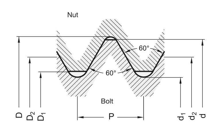
For thread pitch reference, DIN 934 footnote P points to DIN 13. In this repo, the available DIN 13 extract confirms the overlap only for M 2,5 through M 24. For larger DIN 934 sizes, this article preserves the DIN 934 values without extending the DIN 13 pitch chart beyond the supplied extract.
How to Read the DIN 934 Dimensions
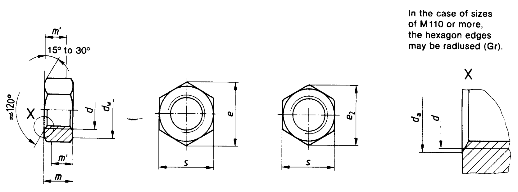
DIN 934 dimension tables are easier to use when the terms are separated into function groups: thread-related diameters, wrenching geometry, and nut height. The diagram below is a clean redraw of the source illustration used to read the table.
DIN 934 Dimension Table (Table 1)
The tables below transcribe the supplied DIN 934 Table 1 in source-aligned blocks. Decimal commas and bracketed sizes are preserved exactly. Dimensions are in millimetres.
Sizes shown in brackets should be avoided if possible. For widths across flats up to and including 4 mm, the source notes a deviation from ISO 4759 Part 1. It also permits minimum dimensions corresponding to tolerance zone h14 instead of h13 for hot-dip galvanized nuts from M 5 to M 16.
Table 1A: M 1 to (M 7)
| Dimension | M 1 | M 1,2 | M 1,4 | M 1,6 | M 2 | M 2,5 | M 3 | (M 3,5) | M 4 | M 5 | M 6 | (M 7) |
|---|---|---|---|---|---|---|---|---|---|---|---|---|
| P | 0,25 | 0,25 | 0,3 | 0,35 | 0,4 | 0,45 | 0,5 | 0,6 | 0,7 | 0,8 | 1 | 1 |
| da min. | 1 | 1,2 | 1,4 | 1,6 | 2 | 2,5 | 3 | 3,5 | 4 | 5 | 6 | 7 |
| da max. | 1,15 | 1,4 | 1,6 | 1,84 | 2,3 | 2,9 | 3,45 | 4 | 4,6 | 5,75 | 6,75 | 7,75 |
| dw min. | 2 | 2,1 | 2,1 | 2,4 | 3,2 | 4,1 | 4,5 | 5 | 5,8 | 6,8 | 8,8 | 9,5 |
| e min. | 2,71 | 3,28 | 3,28 | 3,41 | 4,32 | 5,45 | 6,01 | 6,58 | 7,66 | 8,79 | 11,05 | 12,12 |
| m max. = nominal size | 0,8 | 1 | 1,2 | 1,3 | 1,6 | 2 | 2,4 | 2,8 | 3,2 | 4 | 5 | 5,5 |
| m min. | 0,55 | 0,75 | 0,95 | 1,05 | 1,35 | 1,75 | 2,15 | 2,55 | 2,9 | 3,7 | 4,7 | 5,2 |
| m′ min. | 0,44 | 0,6 | 0,76 | 0,84 | 1,08 | 1,4 | 1,72 | 2,04 | 2,32 | 2,96 | 3,76 | 4,16 |
| s max. = nominal size | 2,5 | 3 | 3 | 3,2 | 4 | 5 | 5,5 | 6 | 7 | 8 | 10 | 11 |
| s min. | 2,4 | 2,9 | 2,9 | 3,02 | 3,82 | 4,82 | 5,32 | 5,82 | 6,78 | 7,78 | 9,78 | 10,73 |
Table 1B: M 8 to M 20
| Dimension | M 8 | M 10 | M 12 | (M 14) | M 16 | (M 18) | M 20 |
|---|---|---|---|---|---|---|---|
| Thread size (d) | M 8 x 1 | M 10 x 1 M 10 x 1,25 | M 12 x 1,5 M 12 x 1,25 | (M 14 x 1,5) – | M 16 x 1,5 – | (M 18 x 1,5) (M 18 x 2) | M 20 x 2 M 20 x 1,5 |
| P | 1,25 | 1,5 | 1,75 | 2 | 2 | 2,5 | 2,5 |
| da min. | 8 | 10 | 12 | 14 | 16 | 18 | 20 |
| da max. | 8,75 | 10,8 | 13 | 15,1 | 17,3 | 19,5 | 21,6 |
| dw min. | 11,3 | 15,3 | 17,2 | 20,2 | 22,2 | 25,3 | 28,2 |
| e min. | 14,38 | 18,9 | 21,1 | 24,49 | 26,75 | 29,56 | 32,95 |
| m max. = nominal size | 6,5 | 8 | 10 | 11 | 13 | 15 | 16 |
| m min. | 6,14 | 7,64 | 9,64 | 10,3 | 12,3 | 14,3 | 14,9 |
| m′ min. | 4,91 | 6,11 | 7,71 | 8,24 | 9,84 | 11,44 | 11,92 |
| s max. = nominal size | 13 | 17 | 19 | 22 | 24 | 27 | 30 |
| s min. | 12,73 | 16,73 | 18,67 | 21,67 | 23,67 | 26,16 | 29,16 |
Table 1C: (M 22) to (M 39)
| Dimension | (M 22) | M 24 | (M 27) | M 30 | (M 33) | M 36 | (M 39) |
|---|---|---|---|---|---|---|---|
| Thread size (d) | (M 22 x 1,5) (M 22 x 2) | M 24 x 2 – | (M 27 x 2) – | M 30 x 2 – | (M 33 x 2) – | M 36 x 3 – | (M 39 x 3) – |
| P | 2,5 | 3 | 3 | 3,5 | 3,5 | 4 | 4 |
| da min. | 22 | 24 | 27 | 30 | 33 | 36 | 39 |
| da max. | 23,7 | 25,9 | 29,1 | 32,4 | 35,6 | 38,9 | 42,1 |
| dw min. | 29,5 | 33,2 | 38 | 42,7 | 46,6 | 51,1 | 55,9 |
| e min. | 35,03 | 39,55 | 45,2 | 50,85 | 55,37 | 60,79 | 66,44 |
| m max. = nominal size | 18 | 19 | 22 | 24 | 26 | 29 | 31 |
| m min. | 16,9 | 17,7 | 20,7 | 22,7 | 24,7 | 27,4 | 29,4 |
| m′ min. | 13,52 | 14,16 | 16,56 | 18,16 | 19,76 | 21,92 | 23,52 |
| s max. = nominal size | 32 | 36 | 41 | 46 | 50 | 55 | 60 |
| s min. | 31 | 35 | 40 | 45 | 49 | 53,8 | 58,8 |
Table 1D: M 42 to M 64
| Dimension | M 42 | (M 45) | M 48 | (M 52) | M 56 | (M 60) | M 64 |
|---|---|---|---|---|---|---|---|
| Thread size (d) | M 42 x 3 | (M 45 x 3) | M 48 x 3 | (M 52 x 3) | M 56 x 4 | (M 60 x 4) | M 64 x 4 |
| P | 4,5 | 4,5 | 5 | 5 | 5,5 | 5,5 | 6 |
| da min. | 42 | 45 | 48 | 52 | 56 | 60 | 64 |
| da max. | 45,4 | 48,6 | 51,8 | 56,2 | 60,5 | 64,8 | 69,1 |
| dw min. | 60,6 | 64,7 | 69,4 | 74,2 | 78,7 | 83,4 | 88,2 |
| e min. | 71,3 | 76,95 | 82,6 | 88,25 | 93,56 | 99,21 | 104,86 |
| m max. = nominal size | 34 | 36 | 38 | 42 | 45 | 48 | 51 |
| m min. | 32,4 | 34,4 | 36,4 | 40,4 | 43,4 | 46,4 | 49,1 |
| m′ min. | 25,9 | 27,5 | 29,1 | 32,3 | 34,7 | 37,1 | 39,3 |
| s max. = nominal size | 65 | 70 | 75 | 80 | 85 | 90 | 95 |
| s min. | 63,1 | 68,1 | 73,1 | 78,1 | 82,8 | 87,8 | 92,8 |
Table 1E: (M 68) to M 100 x 6
| Dimension | (M 68) | M 72 x 6 | (M 76 x 6) | M 80 x 6 | (M 85 x 6) | M 90 x 6 | M 100 x 6 |
|---|---|---|---|---|---|---|---|
| Thread size (d) | (M 68 x 4) | M 72 x 4 | (M 76 x 4) | M 80 x 4 | (M 85 x 4) | M 90 x 4 | M 100 x 4 |
| P | 6 | – | – | – | – | – | – |
| da min. | 68 | 72 | 76 | 80 | 85 | 90 | 100 |
| da max. | 73,4 | 77,8 | 82,1 | 86,4 | 91,8 | 97,2 | 108 |
| dw min. | 92,9 | 97,7 | 102,4 | 107,2 | 111,9 | 121,1 | 135,4 |
| e min. | 110,51 | 116,16 | 121,81 | 127,46 | 133,11 | 144,08 | 161,02 |
| m max. = nominal size | 54 | 58 | 61 | 64 | 68 | 72 | 80 |
| m min. | 52,1 | 56,1 | 59,1 | 62,1 | 66,1 | 70,1 | 78,1 |
| m′ min. | 41,7 | 44,9 | 47,3 | 49,7 | 52,9 | 56,1 | 62,5 |
| s max. = nominal size | 100 | 105 | 110 | 115 | 120 | 130 | 145 |
| s min. | 97,8 | 102,8 | 107,8 | 112,8 | 117,8 | 127,5 | 142,5 |
Table 1F: M 110 x 6 to M 160 x 6
| Dimension | M 110 x 6 | M 125 x 6 | M 140 x 6 | M 160 x 6 |
|---|---|---|---|---|
| Alternative thread size | M 110 x 4 | M 125 x 4 | – | – |
| da min. | 110 | 125 | 140 | 160 |
| da max. | 119 | 135 | 151 | 171 |
| dw min. | 144,9 | 168,6 | 185,6 | 214,1 |
| e min. | 172,32 | 200,57 | 220,80 | 254,70 |
| e2 | 170 | 196 | 216 | 248 |
| m max. = nominal size | 88 | 100 | 112 | 128 |
| m min. | 85,8 | 97,8 | 109,8 | 125,5 |
| m′ min. | 68,6 | 78,2 | 87,8 | 100 |
| s max. = nominal size | 155 | 180 | 200 | 230 |
| s min. | 152,5 | 177,5 | 195,4 | 225,4 |
The source note under the concluded table states that sizes shown in brackets should be avoided if possible. It also identifies P as the coarse-thread pitch from DIN 13 Part 12 and flags special tolerance handling for hot-dip galvanized nuts.
Technical Delivery Conditions and Property Classes
DIN 934 does more than list nut dimensions. The technical-delivery section ties the geometry back to thread tolerance, material family, property class, product grade, and surface condition.
- Thread tolerance: the source specifies 6H for the nut thread and points to DIN 13 Parts 12 and 15.
- Steel nuts: property class 6 up to M 2,5; classes 6, 8, or 10 between M 3 and M 39; above M 39 subject to agreement, with DIN 267 Part 4 referenced.
- Stainless steel nuts: up to M 39 the source lists A2-70 or A4-70; above M 39 subject to agreement, with DIN 267 Part 11 referenced.
- Non-ferrous metal nuts: subject to agreement, with DIN 267 Part 18 referenced.
- Product grade: up to M 16 the source assigns grade A; larger sizes grade B, with geometrical tolerances tied to ISO 4759 Part 1.
DIN 934 notes that when a protective coating is applied, especially electroplated coatings on 6H nuts, it may be necessary to select a larger fundamental deviation than the H position. The source also warns that this can impair the resistance of the bolt-and-nut assembly to stripping.
That warning matters commercially as much as technically. It is one reason buyers should align finish, tolerance, and inspection expectations during the RFQ stage rather than after plating or galvanizing has already been completed. This links directly to material certification for critical hardware and to disciplined route planning in a drawing-to-part workflow.
Designation Examples from DIN 934
The supplied standard gives explicit designation formats for standard, graded, and radiused-edge nuts. Clear examples visible in the source include:
Hexagon nut DIN 934 – M 20 – 8 – Awhen product grade A must be included for a size where it is not the default assumption.Hexagon nut DIN 934 – M 110 x 6 – 8 – Grfor nuts supplied with radiused edges.Hexagon nut DIN 934 – M 12 – 6 AUwhen free-cutting steel is specified by adding the symbol AU to the property-class marking.
Mass Table Relevance
DIN 934 Table 3 gives approximate mass values for steel nuts based on a density of 7,85 kg/dm³ and states that the values are for guidance only. The source also states that approximately the same mass values may be assumed for fine pitch nuts.
That makes the mass table useful for RFQ planning, packing estimates, and dispatch calculations, but it should not be treated as a substitute for actual batch weight when the order is cost-sensitive or shipping-sensitive. If you need the downstream process discipline behind that kind of estimate, our custom component machining and industrial equipment parts pages show how drawing, process route, and inspection planning usually connect in real orders.
Appendix A: Additional Spare-Parts Thread Sizes
Appendix A in the supplied source treats M 1,7, M 2,3, and M 2,6 as previous thread sizes that should no longer be used for the international selection of bolts, screws, and nuts. The source allows them only where spare-parts needs require hardware in accordance with an older DIN 934 edition.
| Dimension | M 1,7 | M 2,3 | M 2,6 |
|---|---|---|---|
| P | 0,35 | 0,45 | 0,45 |
| da min. / max. | 1,7 / 1,95 | 2,3 / 2,64 | 2,6 / 3 |
| e min. | 3,82 | 4,88 | 5,45 |
| dw min. | 2,7 | 3,6 | 4,1 |
| m max. / min. | 1,4 / 1,15 | 1,8 / 1,55 | 2 / 1,75 |
| m′ min. | 0,92 | 1,24 | 1,4 |
| s max. / min. | 3,5 / 3,38 | 4,5 / 4,32 | 5 / 4,82 |
| Mass for 1000 units, kg ≈ | 0,10 | 0,20 | 0,72 |
Common Selection and Application Mistakes
- Assuming every DIN 934 size uses the same product grade instead of checking the A/B split at M 16.
- Treating bracketed sizes as preferred purchasing sizes when the source explicitly says they should be avoided if possible.
- Missing the coating warning and approving plated or galvanized nuts without confirming fit and stripping resistance.
- Using older width-across-flats habits without checking the ISO-era transition note in the standard.
- Quoting a nut only by nominal size and property class without clarifying designation, grade, finish, and thread requirement.
Legacy Width Across Flats vs ISO-Era Change
The explanatory notes in the supplied DIN 934 source compare previous widths across flats with the newer widths across flats in ISO 272 for a few commercially important sizes. That comparison is one of the most useful checks when older spare-part drawings meet newer procurement chains.
| Thread size | Previous width across flats, mm | New width across flats as in ISO 272, mm |
|---|---|---|
| M 10 | 17 | 16 |
| M 12 | 19 | 18 |
| M 14 | 22 | 21 |
| M 22 | 32 | 34 |
Where DIN 934 Matters in Real Manufacturing
DIN 934 matters whenever a buyer, plant engineer, or machine shop needs one of the following: correct nut envelope dimensions, a controlled bearing face, compatibility with a DIN 13 thread designation, or a clear basis for finish and property-class discussion.
- Spare-part replacement: Older equipment often still references legacy DIN hardware, especially when dimensions around the wrenching envelope matter.
- Drawing-based supply: Built-to-print jobs need the nut size, thread, grade, finish, and designation format to be locked before production starts.
- Coated fasteners: Zinc-plated or hot-dip galvanized nuts need tolerance awareness, not just nominal-size matching.
- Industrial RFQs: Comparing vendors is easier when the buyer separates thread standard, nut geometry, property class, and finish instead of combining them into one vague line item.
If your application needs custom hardware supply around a standard thread or nut envelope, those requirements usually sit next to machining, traceability, and inspection planning rather than apart from them. That is why teams handling custom component machining, industrial equipment parts, or even material substitution decisions in steel standards comparisons need the same discipline early in the RFQ.