From Drawing to Part: Our Step-by-Step Machining Workflow
The Ayask Steel Engineering Team writes for plant buyers, project engineers, and procurement teams sourcing custom steel components as per drawing. Our perspective comes from 40+ years of manufacturing rolling mill components, replacement parts, and fabricated-and-machined assemblies where fit, function, delivery, and documentation all matter.
- 40+ years of continuous manufacturing operations
- Experience with replacement parts, shutdown support, and project-based industrial manufacturing
- Built-to-print fabrication and machining for OEMs, EPCs, steel plants, and maintenance teams
Have you ever wondered what happens after you email us a drawing? How does a PDF become a 500kg precision steel assembly arriving at your factory gate?
Transparency is key to trust. Today, we're pulling back the curtain on the Ayask Steel manufacturing workflow. Here is the journey of typical custom component.
Phase 1: Engineering Review & Planning
Before a single chip is cut, our engineering team dissects the requirement.
- Design for Manufacturing (DFM): We check for feasible tolerances, tool access issues, and suggest optimizations to reduce cost without compromising function.
- Process Planning: We create a "Route Sheet"—a roadmap listing every operation, machine, and inspection point.
- Material Strategy: We determine the raw stock size (adding machining allowances) and identify the correct grade.
Phase 2: Material Sourcing & Prep
We pull the raw material from our stock or order it from certified mills.
- Incoming QC: The material is checked for dimensions and MTC verification.
- Sawing/Cutting: The raw bar or plate is cut to the blank size.
Phase 3: Rough Machining
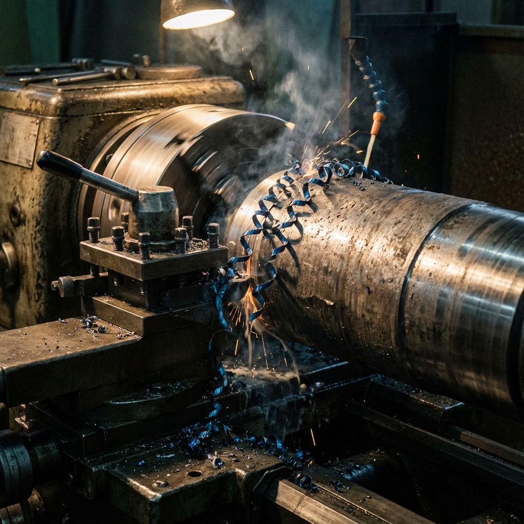
The goal here is heavy material removal.
- Turning/Milling: We remove the bulk of the material, leaving usually 2-3mm of "green stock" on all surfaces.
- Reasoning: Heavy machining introduces stress. We leave material so that any distortion can be corrected later.
Phase 4: Stress Relieving (Optional but Recommended)
For complex or large parts, rough machining releases internal stresses that warp the part.
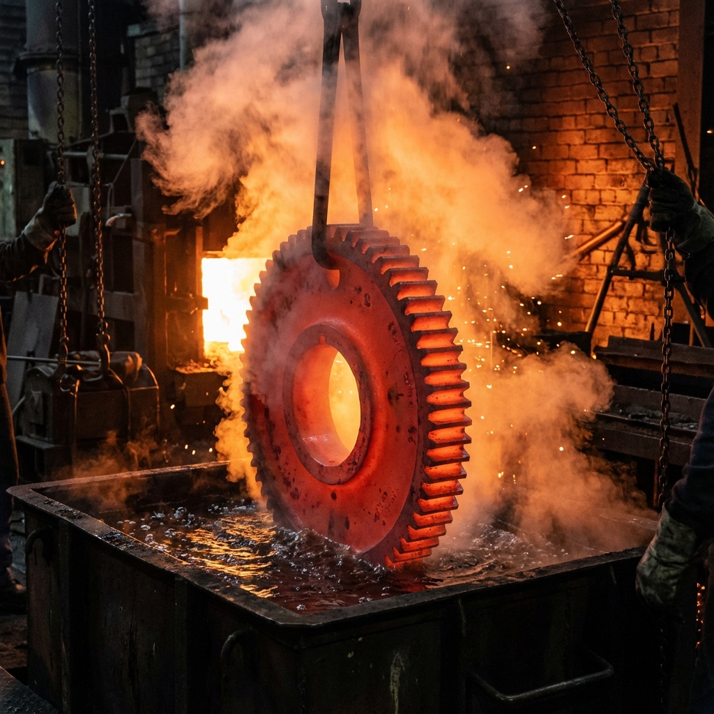
- Normalization/Stress Relief: The part is heated in a furnace and slowly cooled to relax the molecular structure. This ensures the part stays straight during finishing.
Phase 5: Finish Machining
This is where precision happens.
- Setup: Using precision fixtures and soft jaws to avoid marring the part.
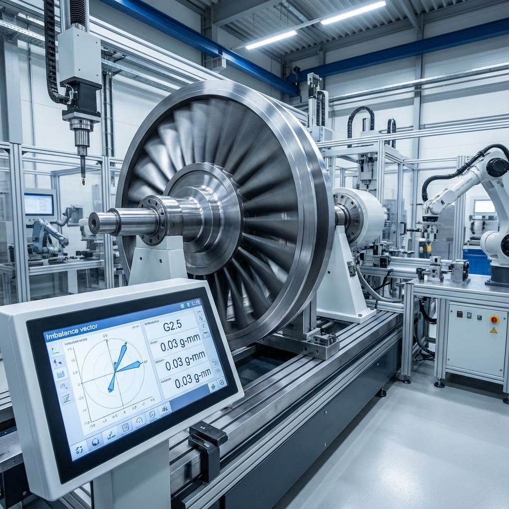
- Operation: Fine cuts with high-quality inserts to achieve the final dimensions and surface finish (Ra value).
- Tolerances: We chase microns here, typically holding tolerances of ±0.02mm or tighter as specified.
Phase 6: Quality Control (QC)
The part moves to the inspection table.
- Dimensional Check: Micrometers, verniers, and bore gauges verify all critical dimensions against the drawing.
- NDT (Non-Destructive Testing): If required, we perform Dye Penetrant (DP) or Ultrasonic Testing (UT) to check for surface or internal cracks.
- Functional Check: Threads are checked with Go/No-Go gauges; mating parts are assembled to check fitment.
Phase 7: Dispatch
- Preservation: Machined surfaces are coated with rust-preventive oil (like Rust-X).
- Packing: Parts are wrapped in VCI paper, bubble wrap, and secured in wooden crates or pallets.
- Documentation: Invoice, MTCs, and Inspection Reports are attached.
Frequently Asked Questions
What file formats do you need to start manufacturing?
What is DFM (Design for Manufacturing)?
Why is stress relieving important?
Do you provide Material Test Certificates (MTC)?
What happens during the QC phase?
Conclusion
Manufacturing is a symphony of coordinated steps. By strictly adhering to this workflow, we minimize errors, ensure consistency, and deliver parts that work right out of the box.
Do you have a complex drawing that needs execution? Send it to us for a quote.