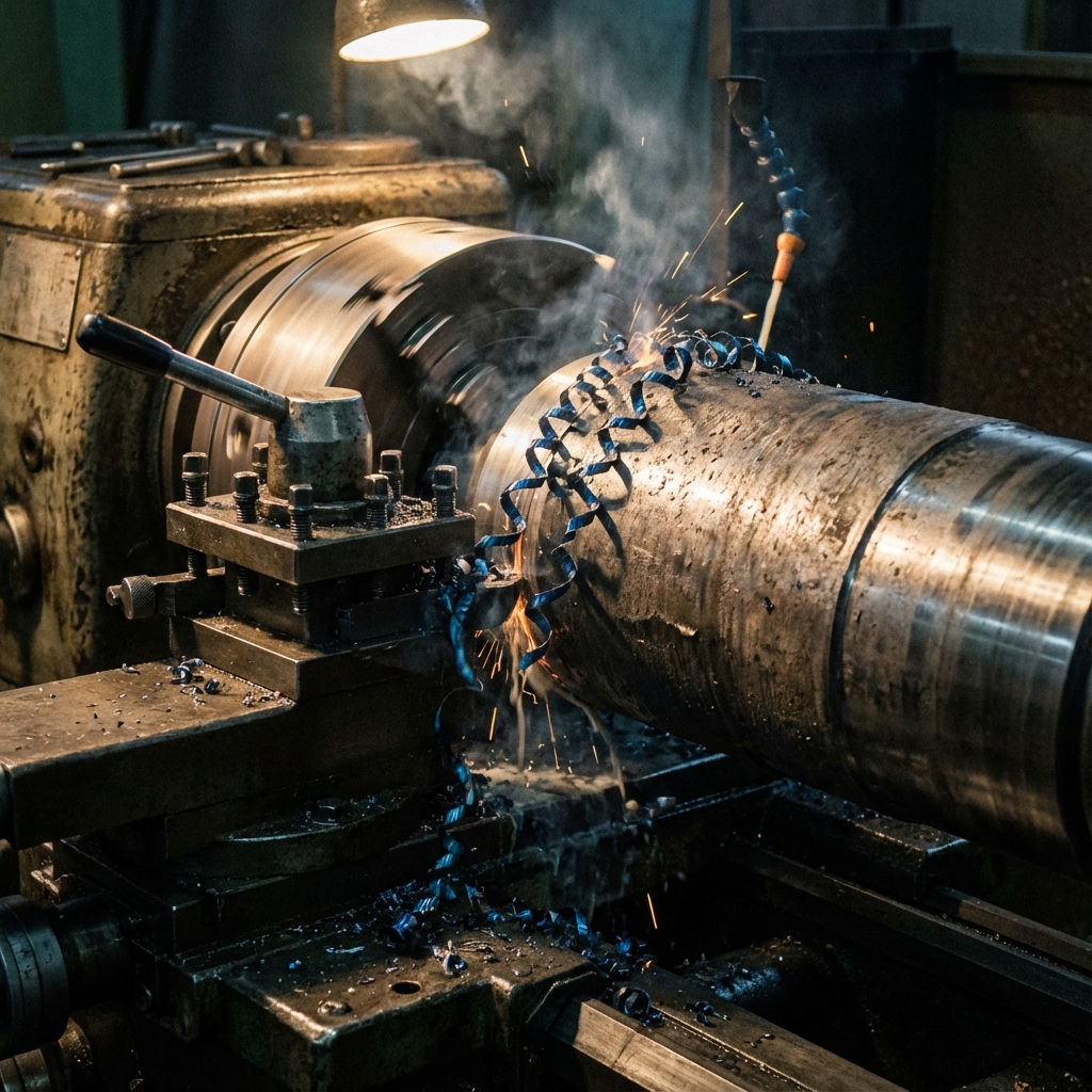
Large Shaft Turning for Tight Bearing Journal Tolerances
The Ayask Steel Engineering Team writes for plant buyers, project engineers, and procurement teams sourcing custom steel components as per drawing. Our perspective comes from 40+ years of manufacturing rolling mill components, replacement parts, and fabricated-and-machined assemblies where fit, function, delivery, and documentation all matter.
- 40+ years of continuous manufacturing operations
- Experience with replacement parts, shutdown support, and project-based industrial manufacturing
- Built-to-print fabrication and machining for OEMs, EPCs, steel plants, and maintenance teams
"Large shaft turning is won by process control, not by claiming impossible numbers. Support strategy, thermal stability, tooling, and inspection decide whether a journal fits in the field or fails at assembly."
Large shaft turning becomes difficult when the shaft is long, heavy, heat-sensitive, and functionally tied to bearing fits, seals, or rotating equipment. On these jobs, the real challenge is not just hitting a nominal diameter. It is holding size, runout, straightness, surface finish, and concentricity at the same time.
The phrase "micron-level tolerance" is often used too loosely in machining marketing. In practice, large shafts are usually controlled in tens of microns on critical diameters, while the final process depends on the drawing. Finish turning may be enough for some journals, but cylindrical grinding is commonly planned from the start when the drawing demands tighter form control, lower surface roughness, or hardened running surfaces.
Quick Answer
- Large shafts rarely succeed on machine capability alone; support, thermal control, and metrology matter just as much.
- Finish turning commonly establishes geometry and leaves a predictable surface, but very tight journals often move to cylindrical grinding for the last size-critical step.
- Buyers should specify fit class, datum strategy, runout or cylindricity limits, surface finish, heat-treatment condition, and inspection requirements up front.
Can Turning Alone Hold Micron-Level Tolerances on a Large Shaft?
Sometimes, but not always. Under normal conditions, turning is commonly associated with broader tolerance capability than cylindrical grinding, and many large shafts use turning to establish the axis, shoulders, and stock condition before the final journal process is chosen. If the drawing calls for a fit class on a bearing seat, very low runout, or a fine finish such as Ra 0.8 or Ra 0.4, grinding is often the more dependable final step.
| Requirement | Typical Planning Decision |
|---|---|
| General shaft diameters with controlled turning tolerances | Rough and finish turning may be sufficient if form and finish requirements are moderate. |
| Bearing journals with tight fit, low runout, or stricter form control | Leave controlled stock after turning and plan cylindrical grinding as the final sizing operation. |
| Hardened running surfaces or post-heat-treatment correction | Use hard turning only where the setup is stable and the drawing allows it; otherwise plan grinding. |
That distinction matters commercially as well as technically. If the RFQ only says "tight tolerance shaft," the supplier still has to interpret whether the final control is dimensional, geometric, surface-related, or all three.
The Variables That Actually Decide Accuracy
1. Deflection and Work Support
A long shaft bends under its own weight and also under cutting force. That means the problem is not only "diameter error." It can also show up as taper, poor straightness, chatter, unstable runout, or shoulders that no longer relate correctly to the journal axis.
- Support method: Chuck, tailstock, and steady rests have to work as one system rather than as separate accessories.
- Prepared support bands: Steady-rest rollers should run on a machined support band, not on rough scale or irregular stock.
- Support location: Theoretical placement helps, but final positions still need proving by indicator checks, trial cuts, and observed chatter behavior.
2. Thermal Growth
Steel expands with temperature, and large diameters make that growth meaningful very quickly. The planning formula is simple:
Thermal Expansion Check
delta = alpha x length x temperature change
For carbon steel, a planning value of about 11.7 micrometers per meter per degree C is commonly used.
On a 500 mm journal, a 10 degree C rise changes diameter by about:
0.5 x 11.7 x 10 = 58.5 micrometers
If you size the journal while it is hot and inspect it only after it cools, the part can drift badly enough to miss the fit class.
That is why disciplined shops do not jump straight from heavy roughing to final sizing on critical journals.
- Semi-finish first: Leave a predictable allowance after heavy stock removal.
- Let the part stabilize: Coolant helps the cutting zone, but it does not guarantee the shaft core is back to inspection temperature.
- Measure consistently: Final sizing should be tied to a repeatable part temperature, not just a machine-cycle endpoint.
3. Tool Pressure, Tool Wear, and Surface Finish
Surface finish on a long shaft is never just an insert-choice problem. Feed, nose radius, setup stability, material hardness, and tool wear all change the result.
- Wiper inserts: These are useful on stable setups because they can maintain a good finish at higher feed than conventional finishing geometries.
- Material state matters: For alloy steels such as 4140 or EN24 below the hard-turning range, coated carbide or cermet is often the practical finishing choice.
- Use CBN selectively: CBN is typically chosen for hardened steels in the hard-turning range, not as a default answer for every alloy-steel finish pass.
- Wear control: On long cuts, a worn tool can create taper and finish drift long before it becomes visibly damaged.
4. Metrology and Datum Discipline
The diameter can be correct and the shaft can still fail in service. That happens when the journal size passes, but the datum relationship, runout, roundness, or cylindricity does not.
- Micrometers: Use calibrated large-frame micrometers or comparable bore and journal inspection tooling for the actual size range.
- Runout checks: Check relative to the datum strategy in the drawing, not just relative to how the part happened to sit in the machine.
- Surface finish checks: If a journal calls for a defined Ra, verify it with the appropriate tester instead of assuming the insert geometry guarantees it.
- Inspection support condition: Large shafts should be inspected on a stable support method that reflects the functional axis being controlled.
A Practical Process Plan for Tight-Tolerance Shafts
- Review the drawing first: Confirm fit class, datum scheme, journal finish, heat-treatment condition, and which surfaces are function-critical.
- Plan stock allowances intentionally: Roughing should leave enough material for distortion cleanup, semi-finish correction, and the final sizing method.
- Create support bands early: Machine stable steady-rest contact zones before relying on roller support for the final geometry.
- Separate roughing from final sizing: Semi-finish, allow temperature to stabilize, then take final cuts or shift to grinding.
- Choose the final process by requirement: Finish turning is a process choice, not a badge of honor. If grinding gives more reliable compliance, plan grinding.
- Inspect function, not just dimensions: Confirm size, runout, form, and finish in the same inspection logic the assembly actually cares about.
This is the same thinking that drives our broader drawing-to-part machining workflow. On distortion-prone jobs, it also connects directly with decisions around stress relief and heat treatment.
When Cylindrical Grinding Should Be Planned From the Start
| Situation | Why Grinding Is Often Preferred |
|---|---|
| Critical bearing journals | More dependable control of diameter, roundness, and final surface condition. |
| Post-heat-treatment correction | Grinding is commonly used to recover size and form after distortion risk has already been introduced. |
| Very fine finish requirement | The required Ra may be more repeatable through grinding than through finish turning alone. |
| Rotating equipment that will be balanced or run at speed | Journal form and concentricity become more sensitive to vibration, seal life, and bearing performance. |
If the shaft will go into high-speed rotating service, the machining plan should also be reviewed alongside the balancing plan. That is where our guide on dynamic balancing for rotating spares becomes relevant, because journal quality and balancing quality are closely linked in real equipment.
What Buyers Should Put on the RFQ or Drawing
A better drawing produces a better shaft. If you want the supplier to hold a critical journal correctly, avoid vague notes like "maintain close tolerance."
- Nominal size and fit class: For example, specify the required shaft fit per the applicable nominal size range instead of describing it informally.
- Datum strategy: State which centers, faces, or journals govern runout and concentricity checks.
- Geometric controls: Call out runout, roundness, cylindricity, straightness, or shoulder squareness where they affect function.
- Surface requirement: Put the required Ra only on the surfaces that truly need it.
- Material and condition: Include grade, hardness condition, and whether the part is supplied pre-hardened, quenched and tempered, or to be ground after heat treatment.
- Inspection requirement: State whether you need a routine dimensional report, surface-finish record, material certification, or a more formal inspection package.
If documentation matters for fit, traceability, or vendor approval, it should be stated early. That is why we also recommend aligning shaft RFQs with the same discipline used in material certification and inspection planning.
Frequently Asked Questions
What is a realistic tolerance target for large shaft turning?
Does every large shaft need cylindrical grinding after turning?
Why do steady rests need a machined support band?
When should CBN be used on shaft journals?
What matters more on a bearing journal: diameter or runout?
Conclusion
Tight shaft tolerances are achieved by process design, not by optimistic wording. On large shafts, that means controlling support, heat, wear, datum logic, and final inspection with the same seriousness as the cutting operation itself. When the drawing demands it, the right answer is not to force turning to do everything. The right answer is to combine turning, stabilization, and grinding in the sequence that produces a shaft that fits and runs correctly.
Need a built-to-print shaft quotation? If your drawing includes critical fits, runout limits, or bearing journals, send us the drawing for a technical review so the machining route can be matched to the real tolerance requirement.